Diferencia entre revisiones de «QSG kiBox/en»
De wiki.kiconex
Página creada con «== Hardware Installation ==» |
Sin resumen de edición |
||
| (No se muestran 4 ediciones intermedias de 2 usuarios) | |||
| Línea 9: | Línea 9: | ||
[[Archivo:Kibox4-new-con nombres.png|centro|miniaturadeimagen|Kibox 4 front panel]] | [[Archivo:Kibox4-new-con nombres.png|centro|miniaturadeimagen|Kibox 4 front panel]] | ||
== Hardware installation == | |||
== Hardware | * Before working with kiBox, it is necessary to prepare the installation of the controllers that will be connected to it. The controllers must be connected to each other in cascade (as shown in the image) and directed to the RS485 ports of the kiBox according to the [https://es.wikipedia.org/wiki/Daisy_chain daisy-chain] topology. Use a 3-wire shielded cable. | ||
Note: Do not make derivations or close the circuit. | |||
[[Archivo:QS kibox2 - 2.circuito.png|centro|miniaturadeimagen|Controls connected in daisy-chain to each other.]] | |||
* Connect the RJ45 cable from the Ethernet port on the kiBox2 to the Ethernet LAN port on the router. | |||
[[Archivo:Kibox2 v2024 LAN.jpg|centro|miniaturadeimagen|RJ45 cable connected to kibox2]] | |||
[[Archivo: | |||
Note: RJ45 cable not included, optional to add to your order. | |||
* Before performing this step, '''for your safety, check that there is no connection of the instruments to the electrical network'''. | |||
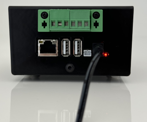
To power the ''kiBox'', simply connect the power cable to its input and then to the mains power supply. | |||
[[Archivo:Kibox2 conectado a red.png|centro|miniaturadeimagen|Kibox 2 connected to the mains with a mains adapter.]] | |||
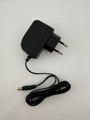
[[Archivo:Adaptador de red kibox v2024.jpg|centro|miniaturadeimagen|Kibox v2024 network adapter]] | |||
* Access our website https://my.kiconex.com, enter your credentials (a [[Newuser|registration]] is required) and click on access. | |||
[[Archivo:QS kibox2 - 5.login mykiconex.png|centro|miniaturadeimagen|myKiconex access platform.]] | |||
* To continue setting up your installation, go to [[User Profile]] or [[Facilities|Facilities]]. We recommend reading the other related sections in [[MainPage|MyKICONEX]]. | |||
* | |||
Revisión actual - 00:01 28 ago 2024
KiBox2-4 Quick Start Guide
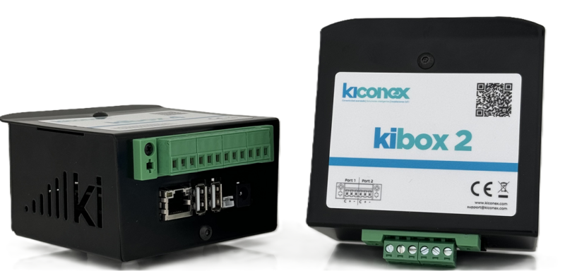
kiBox have been designed as plug & play IoT devices, thus making their installation easy.
In this guide, the user will find simplified information to get their kiBox2-4 up and running and start working with it.
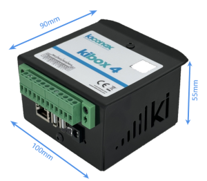
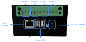
Hardware and dimensions
Hardware installation
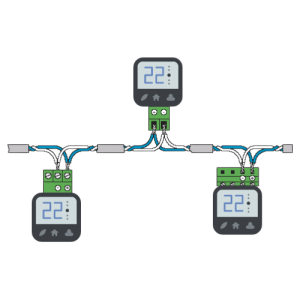
- Before working with kiBox, it is necessary to prepare the installation of the controllers that will be connected to it. The controllers must be connected to each other in cascade (as shown in the image) and directed to the RS485 ports of the kiBox according to the daisy-chain topology. Use a 3-wire shielded cable.
Note: Do not make derivations or close the circuit.
- Connect the RJ45 cable from the Ethernet port on the kiBox2 to the Ethernet LAN port on the router.
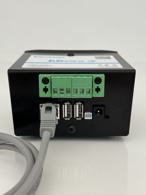
Note: RJ45 cable not included, optional to add to your order.
- Before performing this step, for your safety, check that there is no connection of the instruments to the electrical network.
To power the kiBox, simply connect the power cable to its input and then to the mains power supply.
- Access our website https://my.kiconex.com, enter your credentials (a registration is required) and click on access.

- To continue setting up your installation, go to User Profile or Facilities. We recommend reading the other related sections in MyKICONEX.
