Diferencia entre revisiones de «CONN kiBox/en»
Página creada con «* '''+ (A)''' positive bus connection * '''- (B)''' negative bus connection * '''gnd''' is the ground connection for the shielded cable» |
Sin resumen de edición |
||
| (No se muestran 2 ediciones intermedias de 2 usuarios) | |||
| Línea 1: | Línea 1: | ||
'''For kibox versions v.2023 and earlier, [[CONN kiBox2023|click here]].''' | |||
There are two types of connection for a ''kiBox'': | |||
<gallery widths="300" heights="307"> | <gallery widths="300" heights="307"> | ||
Archivo:Kibox2. | Archivo:Kibox2-4-new.png|Kibox 4 and Kibox 2 | ||
Archivo: | Archivo:V2024 kibox4 CE LQ.png|Kibox installed in a kiconex electrical panel | ||
</gallery> | </gallery> | ||
Below is a list of how to connect a ''kiBox'' according to the two previous options. | |||
<div class="mw-translate-fuzzy"> | |||
== KiBox Connections == | |||
When we have a ''kiBox'' we have all the connections on one of the sides of the device. | |||
</div> | |||
=== 1.- Modbus port connections === | === 1.- Modbus port connections === | ||
The | The kiBox 2 has 2 Modbus RTU (RS485) ports: port 1 located on the left and port 2 located on the right. | ||
The kiBox 4 has 4 Modbus RTU (RS485) ports: ports arranged consecutively, with port 1 located on the far left and port 4 located on the far right. | |||
<div class="mw-translate-fuzzy"> | |||
* '''C''' common bus connection (if the control has one) | |||
* '''<big>+</big>''' positive bus connection | |||
* '''<big>-</big>''' negative bus connection | |||
</div> | |||
<div class="mw-translate-fuzzy"> | |||
It is very important to respect the polarity of the connection and to correctly connect the bus shield to avoid electromagnetic noise. | It is very important to respect the polarity of the connection and to correctly connect the bus shield to avoid electromagnetic noise. | ||
[[Archivo:Kibox2 cables con polaridades.png|centro|miniaturadeimagen|Kibox2 polarities]] | |||
</div> | |||
<div class="mw-translate-fuzzy"> | |||
=== 2.- Network-Internet connection === | |||
To connect to the Internet, the ''kiBox'' must be connected using an RJ45 cable to the connector located at the bottom left. The ''kiBox'' connects to the Internet using a dynamic IP (DHCP). This link indicates how to access the [[kiAdmin]] to be able to modify its network configuration and set a static IP. | |||
[[Archivo:Kibox2 v2024 LAN.jpg|centro|miniaturadeimagen|RJ45 cable connected to kibox2]] | |||
=== 3.- Power connection === | |||
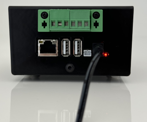
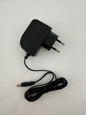
To power the ''kiBox'', simply connect the power cable to its input and this also to the electrical network. | |||
[[Archivo:Kibox2 conectado a red.png|centro|miniaturadeimagen|Kibox 2 connected to the mains with network adapter.]] [[Archivo:Adaptador de red kibox v2024.jpg|centro|miniaturadeimagen|Kibox v2024 network adapter]] | |||
</div> | |||
=== 4.- Switching on the equipment and checking === | |||
After connecting the network adapter to the mains, the kibox should turn on automatically. | |||
To check that it is correctly connected and working, a red LED will appear to the right of the kibox-network adapter connection. | |||
If the internet connection is working correctly, the LEDs on the RJ45 plug (one green and one orange) will flash intermittently. | |||
If these LEDs are static, it means that there is no data transmission with the WWW. | |||
The next steps would be to [[Newuser|create]] a user on the [https://my.kiconex.com myKiconex] platform and register a [[Facilities|facility]]. | |||
<div class="mw-translate-fuzzy"> | |||
== Wiring a kiBox in an electrical panel == | |||
When a kiBox mounted on an electrical panel is ordered, the necessary connections have been taken to a terminal block to help and simplify the connection by the customer. | |||
</div> | |||
<div class="mw-translate-fuzzy"> | |||
'''<u>ATTENTION:</u>''' For your safety, '''work''' with the circuit breaker down, that is, '''with the electrical panel without voltage'''. | |||
=== 1.- Modbus port connections === | |||
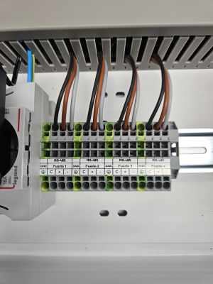
The RS485 bus connections (modbus) are made directly on the terminals as indicated on the terminal block labels. | |||
[[Archivo:Bornero kibox4 v2024 LQ.png|centro|miniaturadeimagen|Bornero kibox4]] | |||
=== 2.- Network-internet connection === | |||
To connect the ''kiBox'' to the internet, it must be connected using an RJ45 cable to the connector located at the bottom left. The ''kiBox'' connects to the internet using a dynamic IP (DHCP). This link indicates how to access the [[kiAdmin]] to be able to modify its network configuration and set a static IP. | |||
[[Archivo:Kibox2 v2024 LAN.jpg|centro|miniaturadeimagen|RJ45 cable connected to kibox2]] | |||
=== 3.- Power connection === | |||
To power the kibox, a 3-wire shielded cable is required. | |||
</div> | |||
The wires will be connected as indicated on the terminal block, being: | |||
*'''C''' common bus connection (if the control has one) | |||
* '''<big>+</big>''' positive bus connection | |||
* '''<big>-</big>''' negative bus connection | |||
* '''GND''' ground connection | |||
<div class="mw-translate-fuzzy"> | <div class="mw-translate-fuzzy"> | ||
== | === 4.- Switching on the equipment and checking === | ||
Finally, once all the connections to the ''kiBox'' have been made correctly, turn on the circuit breaker to supply voltage to the panel. This will start the kibox and all the components of the panel. | |||
</div> | </div> | ||
To check that it is correctly connected and working, a red LED will appear to the right of the kibox-network adapter connection. | |||
If the internet connection is working properly, the RJ45 jack LEDs (one green and one orange) will flash intermittently. | |||
If these LEDs are static, it means that there is no data transmission with the WWW. | |||
The next steps would be to [[Newuser|create]] a user on the [https://my.kiconex.com myKiconex] platform and register a [[Facilities|facility]]. | |||
== Correct wiring between controls == | |||
In kiconex we request a daisy-chain connection, that is, in cascade. | |||
For good practice and to avoid problems, we suggest a correct electrical installation between the controls. To do so, you have this graphic guide that briefly explains how the connections should be made: | |||
[[Archivo:Cableado tierras v2024.jpg|centro|miniaturadeimagen|800x800px|Cable-electrical connection between controls]] | |||
* '''Common:''' if there is a connection for a common cable, a cable will come out of the terminal block (or kibox) that will go from the common to the common of the first control. It is connected to the common and from there a splice comes out to the next control. The operation must be repeated as many controls are going to be connected together in the same port. The common will 'die' in the last control of the series. | |||
* '''+ positive:''' from the terminal block (or kibox, depending on whether there is a kiconex electrical panel) a cable will come out that will go from the positive to the positive of the first control. It is connected to the positive and from there a splice comes out to the next control. The operation must be repeated as many controls are going to be connected together in the same port. The common will 'die' in the last control of the series. | |||
* '''- negative:''' from the terminal block (or kibox, depending on whether there is a kiconex electrical panel) a cable will come out that will go from the negative to the negative of the first control. It is connected to the negative and from there a splice is made to the next control. The operation must be repeated as many controls are going to be connected together in the same port. The common will 'die' in the last control of the series. | |||
* '''GND ground without electrical panel:''' the shield (the covering of the shielded cable) will be connected to the ground of the installation. Between the controls connected in series, the shield must be spliced together. It will 'die' in the last control. | |||
* '''GND ground with electrical panel:''' from the GND terminal block the shield of the shielded cable is connected. The other end must be connected to the shield of the shielded cable of the next control connected in series. The shield will 'die' in the last control. | |||
<blockquote> | |||
<u>Important note:</u> the ground must never be connected to the kibox.</blockquote> | |||
== More information == | |||
If you need more information, you have at your disposal: | |||
* [[Kibox|kiBox wiki]]. There you will find specific information about the kiBox. | |||
* [[MainPage|kiconex wiki]]. It is the generic wiki, which can help you with all the questions you may have on various topics related to Kiconex, its products and its platform. | |||
Revisión actual - 17:11 26 ago 2024
For kibox versions v.2023 and earlier, click here.
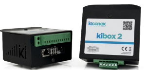
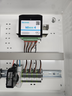
There are two types of connection for a kiBox:
-
Kibox 4 and Kibox 2
-
Kibox installed in a kiconex electrical panel
Below is a list of how to connect a kiBox according to the two previous options.
KiBox Connections
When we have a kiBox we have all the connections on one of the sides of the device.
1.- Modbus port connections
The kiBox 2 has 2 Modbus RTU (RS485) ports: port 1 located on the left and port 2 located on the right.
The kiBox 4 has 4 Modbus RTU (RS485) ports: ports arranged consecutively, with port 1 located on the far left and port 4 located on the far right.
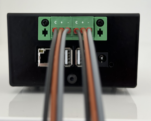
- C common bus connection (if the control has one)
- + positive bus connection
- - negative bus connection
It is very important to respect the polarity of the connection and to correctly connect the bus shield to avoid electromagnetic noise.
2.- Network-Internet connection
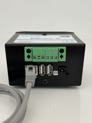
To connect to the Internet, the kiBox must be connected using an RJ45 cable to the connector located at the bottom left. The kiBox connects to the Internet using a dynamic IP (DHCP). This link indicates how to access the kiAdmin to be able to modify its network configuration and set a static IP.
3.- Power connection
To power the kiBox, simply connect the power cable to its input and this also to the electrical network.
4.- Switching on the equipment and checking
After connecting the network adapter to the mains, the kibox should turn on automatically. To check that it is correctly connected and working, a red LED will appear to the right of the kibox-network adapter connection. If the internet connection is working correctly, the LEDs on the RJ45 plug (one green and one orange) will flash intermittently. If these LEDs are static, it means that there is no data transmission with the WWW.
The next steps would be to create a user on the myKiconex platform and register a facility.
Wiring a kiBox in an electrical panel
When a kiBox mounted on an electrical panel is ordered, the necessary connections have been taken to a terminal block to help and simplify the connection by the customer.
ATTENTION: For your safety, work with the circuit breaker down, that is, with the electrical panel without voltage.
1.- Modbus port connections
The RS485 bus connections (modbus) are made directly on the terminals as indicated on the terminal block labels.
2.- Network-internet connection
To connect the kiBox to the internet, it must be connected using an RJ45 cable to the connector located at the bottom left. The kiBox connects to the internet using a dynamic IP (DHCP). This link indicates how to access the kiAdmin to be able to modify its network configuration and set a static IP.

3.- Power connection
To power the kibox, a 3-wire shielded cable is required.
The wires will be connected as indicated on the terminal block, being:
- C common bus connection (if the control has one)
- + positive bus connection
- - negative bus connection
- GND ground connection
4.- Switching on the equipment and checking
Finally, once all the connections to the kiBox have been made correctly, turn on the circuit breaker to supply voltage to the panel. This will start the kibox and all the components of the panel.
To check that it is correctly connected and working, a red LED will appear to the right of the kibox-network adapter connection.
If the internet connection is working properly, the RJ45 jack LEDs (one green and one orange) will flash intermittently.
If these LEDs are static, it means that there is no data transmission with the WWW.
The next steps would be to create a user on the myKiconex platform and register a facility.
Correct wiring between controls
In kiconex we request a daisy-chain connection, that is, in cascade.
For good practice and to avoid problems, we suggest a correct electrical installation between the controls. To do so, you have this graphic guide that briefly explains how the connections should be made:
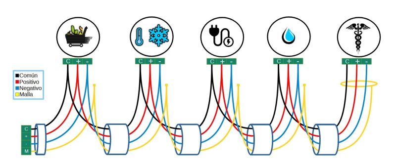
- Common: if there is a connection for a common cable, a cable will come out of the terminal block (or kibox) that will go from the common to the common of the first control. It is connected to the common and from there a splice comes out to the next control. The operation must be repeated as many controls are going to be connected together in the same port. The common will 'die' in the last control of the series.
- + positive: from the terminal block (or kibox, depending on whether there is a kiconex electrical panel) a cable will come out that will go from the positive to the positive of the first control. It is connected to the positive and from there a splice comes out to the next control. The operation must be repeated as many controls are going to be connected together in the same port. The common will 'die' in the last control of the series.
- - negative: from the terminal block (or kibox, depending on whether there is a kiconex electrical panel) a cable will come out that will go from the negative to the negative of the first control. It is connected to the negative and from there a splice is made to the next control. The operation must be repeated as many controls are going to be connected together in the same port. The common will 'die' in the last control of the series.
- GND ground without electrical panel: the shield (the covering of the shielded cable) will be connected to the ground of the installation. Between the controls connected in series, the shield must be spliced together. It will 'die' in the last control.
- GND ground with electrical panel: from the GND terminal block the shield of the shielded cable is connected. The other end must be connected to the shield of the shielded cable of the next control connected in series. The shield will 'die' in the last control.
Important note: the ground must never be connected to the kibox.
More information
If you need more information, you have at your disposal:
- kiBox wiki. There you will find specific information about the kiBox.
- kiconex wiki. It is the generic wiki, which can help you with all the questions you may have on various topics related to Kiconex, its products and its platform.

