Diferencia entre revisiones de «CONN kiBox/en»
Actualizando para coincidir con nueva versión de la página fuente |
Sin resumen de edición |
||
| Línea 8: | Línea 8: | ||
</div> | </div> | ||
==Connection for an standalone kiBox == | ==Connection for an standalone kiBox == | ||
When you have an standalone "kiBox" you have all the connections in one the device's side. | When you have an standalone "kiBox" you have all the connections in one the device's side. | ||
[[Archivo:Conexión kibox 2 2023.jpg|alt=Connections for a kiBox 2|centro|miniaturadeimagen|400x400px|Connetions for a kiBox 2]] | [[Archivo:Conexión kibox 2 2023.jpg|alt=Connections for a kiBox 2|centro|miniaturadeimagen|400x400px|Connetions for a kiBox 2]] | ||
=== 1.- Modbus port connections === | === 1.- Modbus port connections === | ||
The "kiBox" 2 has two modbus RTU ports (RS485): the port 1 is located at the left and the port 2 is located at the right. | The "kiBox" 2 has two modbus RTU ports (RS485): the port 1 is located at the left and the port 2 is located at the right. | ||
kiBox 4 has four modbus RTU ports (RS485): ports arranged consecutively, with port 1 located on the far left and port 4 located on the far right. | |||
kiBox 8 has eight modbus RTU ports (RS485): ports arranged consecutively in two rows: port 1 being located on the far left and port 4 located on the far right in the first row; and port 5 located on the far left and port 8 located on the far right in the second row. | |||
* '''+ (A)''' positive bus connection | * '''+ (A)''' positive bus connection | ||
| Línea 35: | Línea 29: | ||
To power the '''kiBox''' a 3-wire hose is required, connected to the central-bottom connector. The wires to be connected, from left to right, are: ground, line and neutral. The voltage range should be between 88 and 264V AC. With a mains frequency between 47-63Hz. It is important to correctly connect the power supply ground as this will be used to shield the cables connected to the modbus ports. | To power the '''kiBox''' a 3-wire hose is required, connected to the central-bottom connector. The wires to be connected, from left to right, are: ground, line and neutral. The voltage range should be between 88 and 264V AC. With a mains frequency between 47-63Hz. It is important to correctly connect the power supply ground as this will be used to shield the cables connected to the modbus ports. | ||
===4.- Switching on the equipment and verification.=== | === 4.- Switching on the equipment and verification.=== | ||
Finally, once all the ''kiBox'' connections have been correctly made, it is necessary to press the On-Off switch at the bottom right. This switch must be turned on to verify that the ''kiBox'' is powered. The next steps would be to [https://{{SERVERNAME}}/index.php/Special:MyLanguage/NewUser create] a user in the platform [https://my.kiconex.com myKiconex] and to register a [https://{{SERVERNAME}}/index.php/Special:MyLanguage/Facilities installation]. | Finally, once all the ''kiBox'' connections have been correctly made, it is necessary to press the On-Off switch at the bottom right. This switch must be turned on to verify that the ''kiBox'' is powered. The next steps would be to [https://{{SERVERNAME}}/index.php/Special:MyLanguage/NewUser create] a user in the platform [https://my.kiconex.com myKiconex] and to register a [https://{{SERVERNAME}}/index.php/Special:MyLanguage/Facilities installation]. | ||
== Connecting a kiBox on an electrical panel === | == Connecting a kiBox on an electrical panel === | ||
When ordering a ''kiBox'' mounted on an electrical panel, almost all the necessary connections have been carried on a terminal block to help and simplify the connection by the customer. | When ordering a ''kiBox'' mounted on an electrical panel, almost all the necessary connections have been carried on a terminal block to help and simplify the connection by the customer. | ||
=== 1.-Modbus port connections === | === 1.-Modbus port connections === | ||
The RS485 (modbus) bus connections are made directly on the terminals as indicated on the terminal block labels. | The RS485 (modbus) bus connections are made directly on the terminals as indicated on the terminal block labels. | ||
[[Archivo:Bornero Modbus 2P.png|alt=Modbus port connection terminal block|centro|miniaturadeimagen|Modbus port connection terminal block]] | [[Archivo:Bornero Modbus 2P.png|alt=Modbus port connection terminal block|centro|miniaturadeimagen|Modbus port connection terminal block]] | ||
=== 2.-Network-internet connection === | === 2.-Network-internet connection === | ||
| Línea 54: | Línea 46: | ||
Finally, once all the ''kiBox'' connections have been correctly made, it is necessary to make sure that the circuit breaker is turned up and press the On-Off switch at the bottom right. This switch must be turned on to verify that voltage is reaching the ''kiBox''. The next steps would be to [[Newuser|create]] a user in the platform [https://my.kiconex.com myKiconex] and register a [[Facilities|installation]]. | Finally, once all the ''kiBox'' connections have been correctly made, it is necessary to make sure that the circuit breaker is turned up and press the On-Off switch at the bottom right. This switch must be turned on to verify that voltage is reaching the ''kiBox''. The next steps would be to [[Newuser|create]] a user in the platform [https://my.kiconex.com myKiconex] and register a [[Facilities|installation]]. | ||
== More information == | |||
If you need more information, you have at your disposal: | |||
* [[Kibox|kiBox wiki]]. There you will find specific information about the kiBox. | |||
* [[Kibox|wiki | * [[MainPage|kiconex wiki]]. It is the generic wiki, which can help you with all the questions you may have on various topics related to Kiconex, its products and its platform. | ||
* [[MainPage|wiki | |||
Revisión del 16:44 25 sep 2023
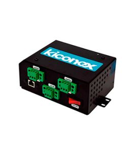
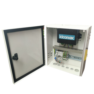
It is possible to have two different "kiBox" versions:
-
kiBox standalone
-
Kibox on electrical pannel
Following, you can find how to connect the "kiBox" depend on the two previous versions:
Connection for an standalone kiBox
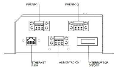
When you have an standalone "kiBox" you have all the connections in one the device's side.

1.- Modbus port connections
The "kiBox" 2 has two modbus RTU ports (RS485): the port 1 is located at the left and the port 2 is located at the right.
kiBox 4 has four modbus RTU ports (RS485): ports arranged consecutively, with port 1 located on the far left and port 4 located on the far right.
kiBox 8 has eight modbus RTU ports (RS485): ports arranged consecutively in two rows: port 1 being located on the far left and port 4 located on the far right in the first row; and port 5 located on the far left and port 8 located on the far right in the second row.
- + (A) positive bus connection
- - (B) negative bus connection
- gnd is the ground connection for the shielded cable
It is very important to respect the polarity of the connection and to correctly connect the bus shield to avoid electromagnetic noise.
2.- Network-internet connection
To connect to the internet, the kiBox must be connected via an RJ45 cable to the connector located at the bottom left. The kiBox connects to the internet via dynamic IP (DHCP). This link shows how to access the kiAdmin to modify your network configuration and set a static IP.
3.- Power supply connection
To power the kiBox a 3-wire hose is required, connected to the central-bottom connector. The wires to be connected, from left to right, are: ground, line and neutral. The voltage range should be between 88 and 264V AC. With a mains frequency between 47-63Hz. It is important to correctly connect the power supply ground as this will be used to shield the cables connected to the modbus ports.
4.- Switching on the equipment and verification.
Finally, once all the kiBox connections have been correctly made, it is necessary to press the On-Off switch at the bottom right. This switch must be turned on to verify that the kiBox is powered. The next steps would be to create a user in the platform myKiconex and to register a installation.
Connecting a kiBox on an electrical panel =
When ordering a kiBox mounted on an electrical panel, almost all the necessary connections have been carried on a terminal block to help and simplify the connection by the customer.
1.-Modbus port connections
The RS485 (modbus) bus connections are made directly on the terminals as indicated on the terminal block labels.

2.-Network-internet connection
To connect to the internet, the kiBox must be connected via an RJ45 cable to the connector located at the bottom left. The kiBox connects to the internet via dynamic IP (DHCP). This link shows how to access the kiAdmin to modify your network configuration and set a static IP.
3.-Power supply connection
To power the kiBox a 3-wire hose is required. The wires would be connected to terminals as indicated on the terminal block. The voltage range must be between 88 and 264V AC. With a mains frequency between 47-63Hz. It is important to correctly connect the power supply ground as this will be used to shield the cables connected to the modbus ports.
4.-Switching on the equipment and verification
Finally, once all the kiBox connections have been correctly made, it is necessary to make sure that the circuit breaker is turned up and press the On-Off switch at the bottom right. This switch must be turned on to verify that voltage is reaching the kiBox. The next steps would be to create a user in the platform myKiconex and register a installation.
More information
If you need more information, you have at your disposal:
- kiBox wiki. There you will find specific information about the kiBox.
- kiconex wiki. It is the generic wiki, which can help you with all the questions you may have on various topics related to Kiconex, its products and its platform.


