Diferencia entre revisiones de «ModbusRTU-RS485/en»
Página creada con «== Modbus RTU-RS485 connection ==» |
Página creada con «=== Steps in connecting RS485 lines with kiconex === 1 - Plan how the controls will be distributed between the different RS485 ports available on the kiBox. The page about [https://{{SERVERNAME}}/index.php/Special:MyLanguage/Planning-route '''facility planning'''] explains this. It is important to take into account the '''characteristics of the Modbus protocol''' when making this plan. The follow…» |
||
| Línea 18: | Línea 18: | ||
* Connection of the screen or mesh of the ground cable at the beginning of the line (kiBox) or at the end of the line, never at the intermediate nodes. | * Connection of the screen or mesh of the ground cable at the beginning of the line (kiBox) or at the end of the line, never at the intermediate nodes. | ||
=== Characteristics that define Modbus RTU communication === | |||
Every control that connects to a Modbus RTU network with an RS485 connector has a series of characteristics or configurations that allow it to communicate through said protocol: | |||
* A '''unique Modbus address''' and different from the rest of the controls connected on the same line. The address value is set between 1 and 247. | |||
* | * A '''communication configuration''', which must be '''the same as all the controls''' connected on that line. Depending on the model and manufacturer of the control, this configuration is static or configurable through parameters. By consulting the manufacturer's manual you can verify this information. The communication configuration variables are: | ||
* | ** Speed or baudrate: 9600bps, 19200bps, etc. | ||
** | ** Data bits: 7 or 8 | ||
** | ** Parity bits: none, even or odd | ||
** | **Stop bits: 1 or 2 | ||
** | |||
=== Steps in connecting RS485 lines with kiconex === | |||
1 - Plan how the controls will be distributed between the different RS485 ports available on the kiBox. The page about [https://{{SERVERNAME}}/index.php/Special:MyLanguage/Planning-route '''facility planning'''] explains this. It is important to take into account the [[ModbusRTU-RS485#Characteristics that define Modbus RTU communication|'''characteristics of the Modbus protocol''']] when making this plan. The following table is indicative when establishing said planning: | |||
1 - | |||
<div lang="es" dir="ltr" class="mw-content-ltr"> | <div lang="es" dir="ltr" class="mw-content-ltr"> | ||
Revisión del 06:43 22 may 2024
Modbus RTU-RS485 connection
The Modbus RTU protocol through RS485 connections is a standard widely used in industrial environments, since it allows the fluid and effective exchange of information over long distances. However, to avoid any possible interference and have completely stable communication, it is necessary that the buses meet a series of requirements that are detailed on this page.
Wiring requirements
- Use of halogen-free shielded cable that provides protection against interference in Modbus RTU communication.
- Distance of at least 20cm with power lines.
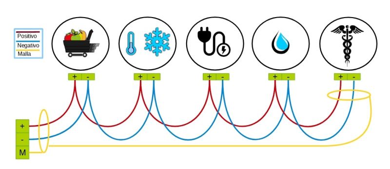
- Connection between devices following a daisy-chain topology, as shown in the following image:

- Respect the polarity of each RS485 connection
- Connection of the screen or mesh of the ground cable at the beginning of the line (kiBox) or at the end of the line, never at the intermediate nodes.
Characteristics that define Modbus RTU communication
Every control that connects to a Modbus RTU network with an RS485 connector has a series of characteristics or configurations that allow it to communicate through said protocol:
- A unique Modbus address and different from the rest of the controls connected on the same line. The address value is set between 1 and 247.
- A communication configuration, which must be the same as all the controls connected on that line. Depending on the model and manufacturer of the control, this configuration is static or configurable through parameters. By consulting the manufacturer's manual you can verify this information. The communication configuration variables are:
- Speed or baudrate: 9600bps, 19200bps, etc.
- Data bits: 7 or 8
- Parity bits: none, even or odd
- Stop bits: 1 or 2
Steps in connecting RS485 lines with kiconex
1 - Plan how the controls will be distributed between the different RS485 ports available on the kiBox. The page about facility planning explains this. It is important to take into account the characteristics of the Modbus protocol when making this plan. The following table is indicative when establishing said planning:
| NOMBRE DEL EQUIPO | PUERTO RS485 | DIRECCIÓN MODBUS |
|---|---|---|
| Identificador del control | Según modelo de kiBox, hasta 8 | Valores de la 1 a la 247 |
2 - Conectar tantos buses o cables apantallados como puertos RS485 se hayan planificado, cada uno de esos buses deben seguir los requisitos de cableado anteriores.
3 - Configurar manualmente en cada control la dirección Modbus planificada en el punto 1.
4 - Verificar que todos los buses Modbus han quedado correctamente realizando una comprobación de los mismos.
5 - Conectar los buses a sus respectivos puertos RS485 en el kiBox, acceder a myKiconex comenzar a operar la instalación en remoto.
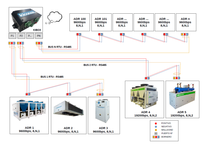
Ejemplo de conexión
En la imagen que aparece más abajo se representa un ejemplo de conexión genérica donde se conectan:
- 3 máquinas marca Intarcon
- 2 máquinas marca Keyter
- N termostatos genéricos
En este ejemplo, el apartado de pasos para la conexión quedaría así:
1 - Distribución de equipos: se realiza una distribución de equipos a partir de su configuración RS485
- Equipos de Intarcon: velocidad 9600, bits de paridad ninguna, bits de parada 1: 9600,8N1
- Equipos de Keyter: velocidad 19200, bits de paridad ninguna, bits de parada 2: 19200,8N2
- Termostatos genéricos: velocidad 9600, bits de paridad ninguna, bits de parada 1: 9600,8N1
| NOMBRE DEL EQUIPO | PUERTO RS485 | DIRECCIÓN MODBUS |
|---|---|---|
| Enfriadora 1 | 1 | 1 |
| Evaporador | 1 | 2 |
| Enfriadora 2 | 1 | 3 |
| Climatizadora 1 | 2 | 4 |
| Climatizadora 2 | 2 | 5 |
| Termp. sala 1 | N | 100 |
| Termp. sala 2 | N | 101 |
| ... | ... | ... |
| Termp. sala N | N | N |
2 - Se conecta el bus 1 con los equipos de Intarcon al puerto 1 y el bus 2 al puerto 2. En el caso del bus N, se conecta a su respectivo puerto, con los N equipos que tenga conectados.
3 - Se configuran en el display de cada máquina las direcciones Modbus de la columna "DIRECCIÓN MODBUS".
4 - Se verifica que cada línea de cable está correcta, empleando multímetro, según indicaciones recogidas en la página de comprobación de la línea RS485.
5 - Se accede a plataforma myKiconex y se empieza a ver información.

