Diferencia entre revisiones de «QSG kibox1A»
De wiki.kiconex
Sin resumen de edición Etiqueta: Reversión manual |
Sin resumen de edición |
||
| Línea 1: | Línea 1: | ||
= Quick Start Guide KiBox0 = | |||
= | |||
KiBox devices are designed as plug & play IoT devices, making their installation straightforward. | |||
<!--T:5--> | <!--T:5--> | ||
In this guide, the user will find simplified information to get their KiBox0 up and running and start working with it. | |||
<!--T:6--> | <!--T:6--> | ||
== Hardware | == Hardware and Dimensions == | ||
In this [https://wiki.kiconex.com/index.php?title=TSP_kibox1A link], you will find the product specifications. | |||
== | == Hardware Installation == <!--T:7--> | ||
Follow these steps to set up the KiBox1A: | |||
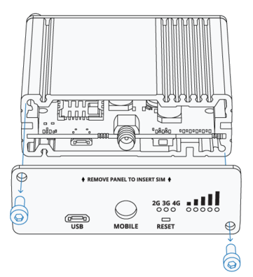
* | * Unscrew the screws on the back panel and remove the casing. | ||
[[Archivo:Desatornillar panel trasero 2.png|centro|miniaturadeimagen|395x395px|Desatornillar panel trasero]] | [[Archivo:Desatornillar panel trasero 2.png|centro|miniaturadeimagen|395x395px|Desatornillar panel trasero]] | ||
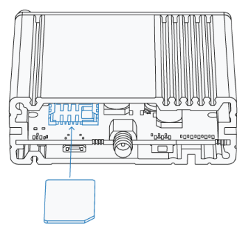
* | * Once the back panel is removed, you will see the SIM card holder. Insert the SIM card into it. | ||
[[Archivo:Insertar SIM.png|centro|miniaturadeimagen|361x361px|Insertar SIM]] | [[Archivo:Insertar SIM.png|centro|miniaturadeimagen|361x361px|Insertar SIM]] | ||
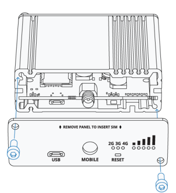
* | * Screw the back panel back on to continue with the installation. | ||
[[Archivo:Atornillar panel trasero.png|centro|miniaturadeimagen|397x397px|Atornillar panel trasero]] | [[Archivo:Atornillar panel trasero.png|centro|miniaturadeimagen|397x397px|Atornillar panel trasero]] | ||
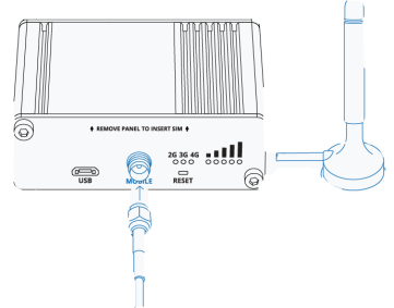
* | * Connect the antenna to the connector labeled "MOBILE". | ||
[[Archivo:Antena.png|centro|miniaturadeimagen|361x361px|Antena]] | [[Archivo:Antena.png|centro|miniaturadeimagen|361x361px|Antena]] | ||
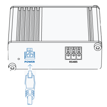
* | * On the front panel, connect the 4-pin power connector. | ||
[[Archivo:Power.png|centro|miniaturadeimagen|362x362px|Power]] | [[Archivo:Power.png|centro|miniaturadeimagen|362x362px|Power]] | ||
* | * Connect the microUSB connector to the port labeled "USB". | ||
[[Archivo:MicroUSB.png|centro|miniaturadeimagen|361x361px|microUSB]] | [[Archivo:MicroUSB.png|centro|miniaturadeimagen|361x361px|microUSB]] | ||
[https://youtu.be/t1gki-r3mMA Quick Start Explainer Video] | |||
With this last step completed, connect the other end of the USB to your computer, which will detect the device in the "Device Manager" and install the necessary drivers. | |||
The next step is to enter the IP "192.168.2.1" to access the KiBox1A configuration. | |||
Revisión del 13:39 27 may 2024
Quick Start Guide KiBox0
KiBox devices are designed as plug & play IoT devices, making their installation straightforward.
In this guide, the user will find simplified information to get their KiBox0 up and running and start working with it.
Hardware and Dimensions
In this link, you will find the product specifications.
Hardware Installation
Follow these steps to set up the KiBox1A:
- Unscrew the screws on the back panel and remove the casing.
- Once the back panel is removed, you will see the SIM card holder. Insert the SIM card into it.
- Screw the back panel back on to continue with the installation.
- Connect the antenna to the connector labeled "MOBILE".
- On the front panel, connect the 4-pin power connector.
- Connect the microUSB connector to the port labeled "USB".
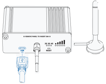
With this last step completed, connect the other end of the USB to your computer, which will detect the device in the "Device Manager" and install the necessary drivers.
The next step is to enter the IP "192.168.2.1" to access the KiBox1A configuration.
