Diferencia entre revisiones de «Translations:ModbusRTU-RS485/6/en»
De wiki.kiconex
Página creada con «=== Characteristics that define Modbus RTU communication === Every control that connects to a Modbus RTU network with an RS485 connector has a series of characteristics or configurations that allow it to communicate through said protocol:» |
Sin resumen de edición |
||
| Línea 1: | Línea 1: | ||
=== | === Wiring requirements === | ||
* Use a halogen-free 3-wire shielded cable that provides protection against interference in Modbus RTU communication. | |||
* Distance of at least 20cm from power lines. | |||
* Respect the polarity of each RS485 connection | |||
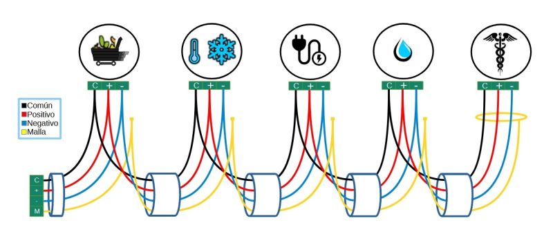
* Connection between devices following a daisy-chain topology, as shown in the following image: | |||
[[File:Cableado tierras v2024.jpg|center|thumbnail|800x800px|Connection of RS485 devices following a daisy-chain topology]] | |||
* '''Common:''' if there is a connection for a common cable, a cable will come out of the terminal block (or kibox) that will go from the common to the common of the first control. It is connected to the common and from there a splice comes out to the next control. The operation must be repeated as many controls are going to be connected together in the same port. The common will 'die' at the last control in the series. | |||
* '''+ positive:''' A cable will come out of the terminal block (or kibox, depending on whether there is a kiconex electrical panel) that will go from the positive to the positive of the first control. It is connected to the positive and from there a splice goes out to the next control. The operation must be repeated as many controls are going to be connected together in the same port. The common will 'die' at the last control in the series. | |||
* '''- negative:''' A cable will come out of the terminal block (or kibox, depending on whether there is a kiconex electrical panel) that will go from the negative to the negative of the first control. It is connected to the negative and from there a splice goes out to the next control. The operation must be repeated as many controls are going to be connected together in the same port. The common will 'die' at the last control in the series. | |||
* '''GND ground without kiconex electrical panel:''' the mesh (the covering of the shielded cable) will be connected to the ground of the installation. Between the controls connected in series, the shield must be connected to each other. It will 'die' in the last control. | |||
* '''GND ground with kiconex electrical panel:''' from the GND terminal block the shield of the shielded cable is connected. The other end must be connected to the shield of the shielded cable of the next control connected in series. The shield will 'die' in the last control. | |||
Revisión actual - 09:31 27 ago 2024
Wiring requirements
- Use a halogen-free 3-wire shielded cable that provides protection against interference in Modbus RTU communication.
- Distance of at least 20cm from power lines.
- Respect the polarity of each RS485 connection
- Connection between devices following a daisy-chain topology, as shown in the following image:

- Common: if there is a connection for a common cable, a cable will come out of the terminal block (or kibox) that will go from the common to the common of the first control. It is connected to the common and from there a splice comes out to the next control. The operation must be repeated as many controls are going to be connected together in the same port. The common will 'die' at the last control in the series.
- + positive: A cable will come out of the terminal block (or kibox, depending on whether there is a kiconex electrical panel) that will go from the positive to the positive of the first control. It is connected to the positive and from there a splice goes out to the next control. The operation must be repeated as many controls are going to be connected together in the same port. The common will 'die' at the last control in the series.
- - negative: A cable will come out of the terminal block (or kibox, depending on whether there is a kiconex electrical panel) that will go from the negative to the negative of the first control. It is connected to the negative and from there a splice goes out to the next control. The operation must be repeated as many controls are going to be connected together in the same port. The common will 'die' at the last control in the series.
- GND ground without kiconex electrical panel: the mesh (the covering of the shielded cable) will be connected to the ground of the installation. Between the controls connected in series, the shield must be connected to each other. It will 'die' in the last control.
- GND ground with kiconex electrical panel: from the GND terminal block the shield of the shielded cable is connected. The other end must be connected to the shield of the shielded cable of the next control connected in series. The shield will 'die' in the last control.
