CONN kibox1A/en
De wiki.kiconex
Kibox1A connection
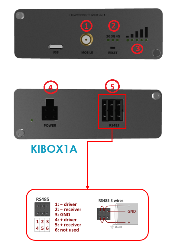
The connection of a kiBox1A can be summarized in three parts: power supply, internet (via GSM network) and connection to the controller (with the RS485 port).
The connection of a kiBox1A is graphically summarized with the following image.

The caption is as follows:
- GSM coverage antenna connector.
- 2G/3G/4G coverage indicator.
- Coverage signal indicator: the signal quality can be checked through the LED indicators. If these indicators are off, it means that a SIM card is not detected or there is no coverage for the kiBox1A to work.
- 9-30Vdc power connector.
- RS485 port using ModBus RTU communications protocol. The control must be connected to the kiBox1A using a 2-wire shielded cable, connecting the shield to the GND pin (3).
More information
If you need more information, you have at your disposal:
- kiBox1A wiki. You will find kiBox specific information.
- kiconex wiki. This is the generic wiki, which can help you with all the doubts you may have on various topics related to kiconex, its products and its platform.
