CheckWiring/en
Checking the RTU-RS485 modbus wiring
Modbus RTU-RS485 wiring should be checked after start-up of the facility and when starting to visualize communication problems on the platform.
You can consult how to make the Modbus RTU-RS485 Connection by clicking on the {SERVERNAME}}/index.php/Special:MyLanguage/ModbusRTU-RS485 link.
If there are errors, with the help of the graphs, you can have a first visualization of these errors. It is possible that only points are displayed, intermittent cuts, false connections in the control (the control appears as connected even though it is not recording data), intermittent disconnections of the controls on the platform, loss of readings on one bus or several, among others.
Below are some graphs where these intermittent communication failures are identified.


Bus measurement
The points that must be taken into account for the checks are the following:
Polarities
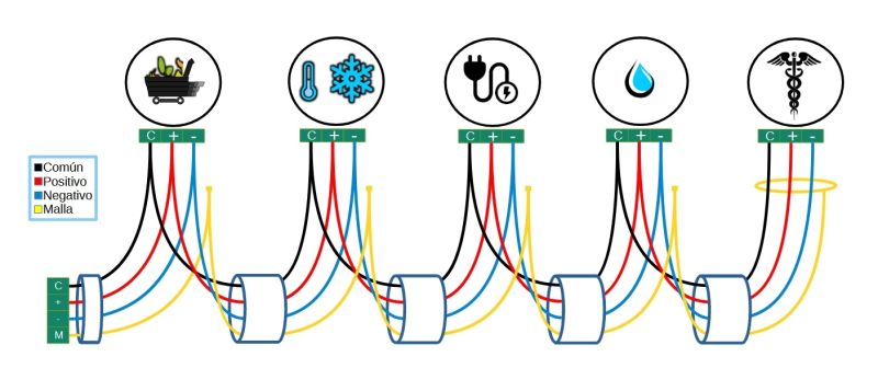
The polarities are those strictly used in the modbus_protocol RTU using the Daisy-chain typology described in the wiring_requirements.

- Common: if there is a connection for a common cable, a cable will come out of the terminal block (or kibox) that will go from the common to the common of the first control. It is connected to the common and from there a splice comes out to the next control. The operation must be repeated as many controls are going to be connected together in the same port. The common will 'die' in the last control of the series.
- + positive: from the terminal block (or kibox, depending on whether there is a kiconex electrical panel) a cable will come out that will go from the positive to the positive of the first control. It is connected to the positive and from there a splice comes out to the next control. The operation must be repeated as many controls are going to be connected together in the same port. The common will 'die' in the last control of the series.
- - negative: from the terminal block (or kibox, depending on whether there is a kiconex electrical panel) a cable will come out that will go from the negative to the negative of the first control. It is connected to the negative and from there a splice is made to the next control. The operation must be repeated as many controls are going to be connected together in the same port. The common will 'die' in the last control of the series.
- GND ground without kiconex electrical panel: the mesh (the covering of the shielded cable) will be connected to the ground of the installation. Between the controls connected in series, the mesh must be spliced together. It will 'die' in the last control.
- GND ground with kiconex electrical panel: from the GND terminal block the mesh of the shielded cable is connected. The other end must be connected to the mesh of the shielded cable of the next control connected in series. The mesh will 'die' in the last control.
They must be connected to each other using the terminal block of the kiconex panel or the kiBox as the start or end of the line, never connecting to the machines or monitored equipment. If the mesh is connected to a machine, the voltage it may have may end up being induced in the communication bus, creating noise and conflicts in it, including the breakage of one or more ports of the kiBox.
Voltage
Voltages in alternating current and direct current must be measured with the help of a multimeter.
The measurements must be made directly on the bus, so the entire bus (positive, negative and mesh) must be DICONNECTED obligatory from the terminal block or from the kiBox if it does not have a panel.
It must be measured between positive-negative, positive-mesh and negative-mesh, both alternating and continuous.
MUST NOT HAVE ANY ALTERNATE VOLTAGE.
In continuous it can possibly have up to 1 Vdc due to the communication flow.
If you have alternating current, you must identify the equipment that is inducing this voltage on the bus and check the wiring to ensure that it is in optimal condition.
The following table may make it easier to collect measurement data:

Continuity
Continuity must be measured between positive-negative, positive-mesh and negative-mesh, this being INEXISTENT.
If there is continuity, the contact that is causing this continuity must be identified and the incident corrected.
To take into account
The communication bus must be away from the power wiring as this can produce noise, the connections within your monitored equipment must also be taken into account.
The bus with NO voltage must be connected to the terminal block of the panel or to the kiBox, this action may lead to failure of the kiBox. If a replacement is made, the buses must be checked before connecting them.
Once the buses have been cleaned and the problematic machines have been isolated, you will have a correct visualization of the readings of the equipment monitored on the platform.
Summary of the previous installation checks.


